| WES A waveform editor for the flexible generation of clock patterns User manual - rev. 1.0 |
Holger Pieper, June 2002
Introduction
1. Purpose
This document contains the user manual of the Waveform Editor Software. It mainly addresses those who deal with CCD applications within a CCD controller environment. The syntax and expressions used throughout the document were defined by the designers of FIERA, which is the name of the ESO state of the art CCD controller.
The Waveform Editor Software was designed to match the special requirements for developers in the FIERA environment. Nevertheless it is a general tool to create and visualize waveforms, a concatenation of electrical pulses, which can be used to control a hardware.
2. Scope
This manual will not give an introduction on the FIERA CCD controller. For detailed information on CCD operation and their characteristics, and for those who are not familiar with the basic FIERA architecture, [1] and [2] will be useful to read.
3. Abbreviations and acronyms
The following abbreviations and acronyms are used in this document :
| CCS | Central Control Software |
| FIERA | Fast Imager Electronic Readout Array |
| HOS | High Level Operating Software |
| HW | Hardware |
| ICS | Instrument Control Software |
| I/O | Input/Output |
| N/A | Not Applicable |
| SW | Software |
| TBC | To Be Confirmed |
| TBD | To Be Defined |
| Tcl/Tk | Tool Command Language/Toolkit |
| UIF | (Portable) User Interface (Toolkit) |
| VLT | Very Large Telescope |
| WAN | Wide Area Network |
| WES | Waveform Editor and Simulator |
| WS | Workstation |
4. Glossary
| Canvas | A widget that allows to display and manipulate various graphical objects like rectangles, lines, bitmaps, and text strings. A Panel X11 window containing widgets. |
| Pattern | Comprises one or several words which are output to the CCD and is confined to one board of the controller. The patterns are written to SRAM from where they are clocked out to the CCD using the selected clockspeed. An example for a pattern is a series of words that are required to shift the charge of a pixel to one of the CCDs output amplifiers. The state of the hardware after the pattern output requires further operation in order to achieve a meaningful result, like reading a pixel. |
| Profile | Defines the transition for a multilevel clock. To use the whole advantage of multi-level clocking, it is possible to define a functional behaviour of a clock phase, i.e. EXP, SINUS, RAMP. With these macros it is possible to design the shape of the rising or falling edge of a phase. |
| Microsequence/Usequence | Contains several patterns which define a operation on the CCD, i.e. reading a pixel. Patterns on different boards are involved to form these instructions which themselves can be chained together to form more complex operations like reading a line. All the patterns in the usequence definition are output to the CCD in parallel. Like patterns, usequences leave the CCD in a undefined state that cannot be used as a starting point for further operations. It is not self-contained. |
| Sequence | A self-contained set of usequences that define the standard operations like integrate, readout or wipe. The sequence contains a set of instructions which are executed sequentially. |
| Widget | A graphic device capable of receiving input from the mouse and the keyboard and communicating with an application or another widget. Each widget is a member of a class that defines its appearance and behaviour. Tk uses X to implement a set of controls with the Motif look and feel. Each widget is implemented using one X window. |
| Word | Set of several bits which are output in parallel. Eight bits are taken together to define a 256-level clock voltage (i.e. multilevel clock). In case of a bilevel clock, each of these bits define the state of a switch, and basically only two rail voltages are being applied to that clock phase. |
5. Applicable documents
- FIERA CCD controller system requirements, VLT-SPE-ESO-13640-1315
- FIERA CCD controller software functional specifications, VLT-SPE-ESO-13640-1315
Overview
The waveform editor has been implemented using the Tcl/Tk and [incr Tcl/Tk] programming languages, making the application most platform independent. It's GUI a common set of commands and options as well as the additional functions relevant for the process of stimuli generation which separates into two different operational environments, a textual and a graphical part. In the following chapters the different operational environments shall be explained in more detail.
Beginning with the Setup chapter a quick tour of how to install the software is given, using the two environments MS-Windows95 and Unix (Solaris and HP-UX) running the standard VLT environment.
The Editor chapter provides information on the editor UIF mainframe and explains the basic set of commands available from the application menu and toolbar.
The Waveforms chapter depicts the usage of the textual and the graphical waveform formats, and the FAQ chapter provides a list of frequently asked questions.
Caution
Since the waveform editor was implemented using an interpreted scripting language, it is obvious that the interpreter, which is sometimes referred to as a sequencer must be present at runtime. The main program loop has not been implemented using C/C++ and does not contain a main (int argc, char *argv[]) function, it is the event loop which is part of the sequencer. This implies that terminating the sequencer will cause the application to stop immediately which may result in unpleasant loss of data.
The waveform definition formats supported by the software, can be manipulated independently. An advantage of this feature is that waveforms, which have been edited manually in either format, input format or output format, can easily be imported into the WES SW. Saving the waveform selected will automatically write both waveform formats to disk, replacing the old files, therefore it is up to the user to decide which version is the most up-to-date one and shall be used for editing.
In order to avoid confusion and eventual loss of data, the user should always choose to work with the same waveform definition format.
Naturally, it cannot be denied that whenever a small change has to be made to a waveform, i.e. changing a clockspeed divider, increasing a repetition factor, it can be much faster and therefore very tempting to edit the file directly using emacs, vi or another common text editor. In case the user does not refrain from this kind of manipulation, unpredictable behaviour of the application and loss of data can occur.
Setup
PC running Windows 95 or Windows NT
| Software environment : | Tcl : 7.6 or higher Tk : 4.2 or higher [incr Tcl/Tk] : 2.2 or higher |
| Step 1 - | Install the Tcl/Tk and [incr Tcl/Tk] SW Download the Tcl/Tk software. The best site to follow the latest updates of [incr Tcl], [incr Tk] respectively, is : A good starting point (amongst numberless others) in order to collect informations, browse the FAQs, investigate other applications built with Tcl is : The PC archives most often are *.zip files which can be unzipped using popular compressing tools or *.exe files which are self-extracting executables and can be executed directly. |
| Step 2 - | Install the WES software Download the WES software from, hang on - dear clustermaster where can I put it...? :-) |
VLT environment
| Step 1 | Login to te13 as fieradev. This is the only machine which has the cmm archiving tools installed. | |
| Step 2 | In ~fieradev run cmmCopy wes, which installes the MODROOT directory structure. | |
| Step 3 | Login to odt as fieradev, change to ~fieradev/wes/src and run make all, which builds the necessary tcl libraries. | |
| Step 4 | Login to odt as fiera, change to ~fieradev/wes/src, and run make install, which installs the SW in the proper INTROOT directory structure. |
Setup of a new project directory
To setup a new project directory proceed as follows:
- Create a blank directory
- Create a new board configuration file myboard.brd which shall contain the board configuration reflecting the physical detector electronics or modify an existing one.
It is essential that the project directory contains a valid board configuration. In case board conflicting board configurations are found in the project directory.
Editor
The waveform editor comprises two different working environments which are both integrated into the application mainframe.
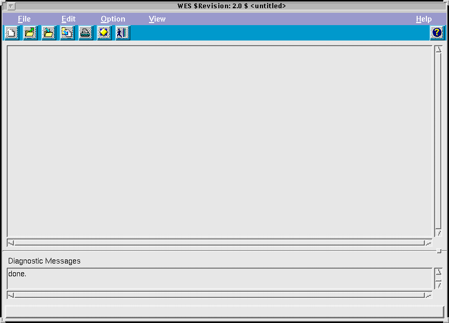 UIF mainframe displaying the text editor panel |
Additionaly a dialog will open which waits for the user to select a project directory :
 Preference dialog |
The project directory initially displayed in the directory entry is loaded from the initialisation file which is optionally created by the SW in the user $(HOME) directory, called .wesFieraCfg. The leading "." makes it a hidden file on UNIX systems. Pressing the browse button opens a dialog which allows to traverse the directory structure :
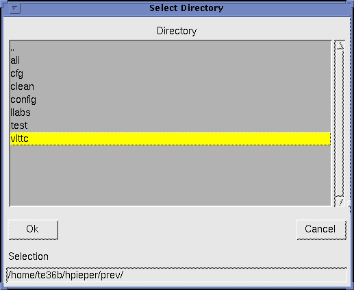 Directory selection |
The system clock speed is assumed to be 50 MHz default, but can be modified to reflect the current HW configuration.
It is essential for a successful session to select a directory containing the detector electronics configuration. In case no entry is selected, error messages will be generated upon opening a waveform definition file, i.e pattern , usequence, or sequence file, or upon creation of a blank definition.
As described in more detail in the Waveforms chapter, the hierarchical waveform definitions are tied to a fixed board configuration. Only SIMMs previously defined in the board configuration file are being accepted by the SW.
Menubar and toolbar
The UIF offers a menubar and a toolbar with user commands, which allow standard file handling operations as well as operations which require a valid waveform definition to be loaded into the editor.
 Menubar |
 Toolbar |
The entry which currently has the focus is displayed with inverted colors, highlighted. In the menubar figure displayed above the mouse cursor has been moved over the Help menu entry.
The five menu buttons File, Edit, Options, View and Help comprise separate sets of items which are explained in the following. Whenever the command listed is also supported as a bitmap button entry in the toolbar, the toolbar button will be displayed additionally.
|
 |
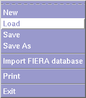
New creates a new waveform definition (pattern, usequence, sequence). When selected the following dialog is displayed : |
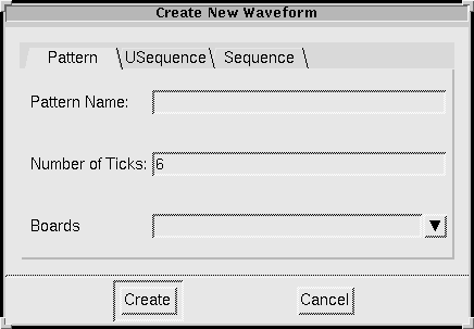 Create new pattern dialog |
Here, you can choose the type of the waveform to create.
Pattern
| Pattern Name | defines the name of the pattern, by which it can be referenced in the hierarchically higher waveform definition of a usequence. As already mentioned, this unique name will also be used to form the filename of the ASCII file to store the waveform. |
| Number of Ticks | gives the length of the pattern in ticks. |
| Boards | sets the detector electronics board, on which the pattern shall be executed. The board entry is a common combobox which contains all the names of the boards present in the board configuration directory (project directory). |
USequence
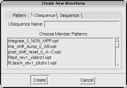 Create new usequence dialog |
| USequence Name | gives the name of the usequence by which it shall be referenced in the hierarchically higher sequence definition. |
| Choose Member Patterns | This listbox contains all patterns present in the project directory. Choosing patterns make them part of the usequence body, upon completing the dialog using the Create button. |
Sequence
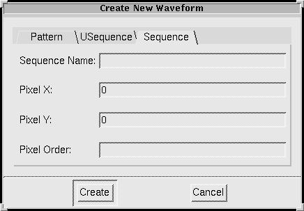 Create new sequence dialog |
| Sequence Name | gives the name of the sequence to be created. |
| Pixel X | specifies the number of pixels to a picture column which are generated for one image. |
| Pixel Y | specifies the number of pixels to a picture row which are generated for one image. |
| Pixel Order | defines the order in which the ports of the CCD are read, i.e. 0,1,2,3 for a 4 port readout. |
 |
Load loads an existing waveform definition from HD. When selected the following Open File Dialog is displayed, which allows to browse the directory structure : |
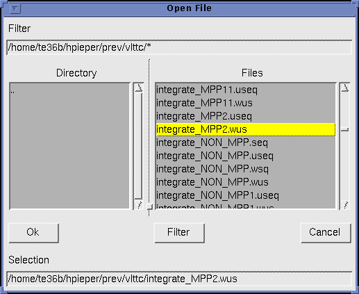 File open dialog |
 |
Save saves the current waveform to HD. |
 |
Save As saves the current waveform with a new name. The File Save Dialog is displayed, which has the same layout as the File Open Dialog, for the user to enter a valid filename which will be used to store the waveform. In case the file already exists, a Confirmation Dialog will popup and wait for the user to confirm the requested operation. |
Import FIERA database imports an existing waveform DB.
Only used to make the user aware of the fact that if he is going to extract waveforms from a file which might contain multiple definitions existing files with the same names as the extracted ones will get overwritten.
 |
Print prints the current waveform. Graphically print out the currently loaded waveform definition. |
 |
Exit exits the application. Displays a Confirmation Dialog for the user to select whether the current configuration, i.e. display configuration, and project path name, shall be saved to the files $(HOME)/.wesFieraCfg and /.wesDisplCfg. |
|
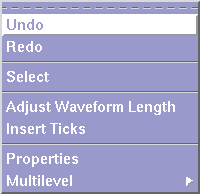
| Undo | undoes the last operation. |
| Redo | redoes the last operation. |
| Select | (This function is not yet implemented.) |
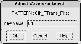 |
Adjust Waveform Length adjusts the length of the current waveform (only applies to PATTERNs and USEQUENCEs). To change the length of the current waveform the new value can be entered in the entryfield. Initially, the current length is displayed. |
||||||
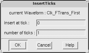 |
Insert Ticks inserts a number of ticks into the current waveform (only works with PATTERNs and USEQUENCEs).
|
|
|
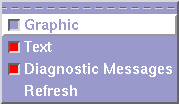
The View menu contains three checkbuttons which indicate the current view configuration. The UIF mainframe can contain both, the graphical and the textual editor panel, plus additionaly a display panel for diagnostic messages.
RED / checked means activated function.
BLUEVIOLET / unchecked means deactivated function.
The displayed figure above has been set to the following :
- Do not diaply the graphical waveform editor.
- Display the textual waveform editor.
- Display the diagnostic messages.
The Refresh command performs an update of the currently active editor panel. In text mode, the text display area is repainted, and in graphic mode the grphical display is repainted as well as the miniature display of the overall waveform (world display).
|
Textual waveform editor
In order to define a waveform textually using the hierarchical waveform definition language, at startup the mainframe window displays the textual environment.
For the actual format of the supported waveform types, please refer to the Waveforms chapter.
Graphical waveform editor
The graphical editor display contains a graphical waveform display as well as additional status information on he selected waveform :
- total length of the waveform in ticks
- the current tick, which the cursor is pointing to
- the current clock frequency (only used in sequence display)
- the current SIMM under the cursor
- the name of the board which hosts the SIMM
- sequence control-statement information, only used in sequence display
- a "world display" which gives an overall view of the entire waveform
- a ruler which displays the current cursor position in ticks
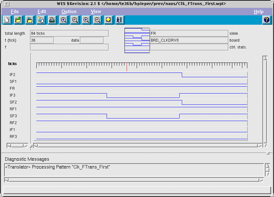 Graphical editor display |
Moving the cursor whithin the waveform display will update the status fields simm board, and tick automatically.
User actions
Additionally to the general operations which can be selected from the Edit Menu, some interactive commands are supported :
| Left Mouse Button Click | Sets the current SIMM at the selected tick. |
| Middle Mouse Button Click | Updates the value of the current SIMM in the data status display. |
| Right Mouse Button Click | Sets the current SIMM starting at selected tick onto the next transition. |
Waveforms
The waveform editor must support two formats used for the description of waveforms. The input format is used to define waveforms textually. WES translates this input format into the output format which serves as the input for the SPArc SW. The files SPArc are then loaded via the sequencer running on the DSP onto the detector electronics, where they are stored.
Both format types, input and output can contain three different kinds of description levels. At the lowest level there is the pattern definition. At the next level, the usequence combines a set of patterns which are executed in parallel by different boards.
Pattern
The pattern definition contains time statements to indicate when a bi-level SIMM is assigned a value. Multilevel pattern definition uses a higher level format because of the following reasons :
- When the patterns are input, the time base which is actually used when the patterns are sent to the controller, is only defined in the sequence definition.
- Say the function is exponential and it would be split into samples according to a certain time base, information on the function behaviour would be deleted and could not be retrieved again.
As mentioned before the following format is used as input to the textual editor, to the graphical editor, and it is also the format that the graphical information is converted into when the editing is finished.
Input-Format
The input format uses the following notation : Bi-Level Pattern
Syntax :
PATTERN <board_name> <pattern_name>
{

     <time_step(i)>
     <time_step(k)>
     <time_step(n)>
     . . .

}
Where i < k < n,
<board_name> must be one of the "well known" names which have been defined either in the file fixed_boards.brd or in the file clk_brds.brd.
<pattern_name> is a NON QUOTED ascii string which the pattern shall be referred by in future definitions. The name must NOT white spaces.
<time_step(i)> has the following format : time i: <simm_name> = <value> ;
The time statement defines the relative timing when a SIMM is assigned a value. The clockspeed will be defined later in the sequence definition. The absolute time can be calculated as i times .
If i > 0 then each of the SIMMs in the pattern are initialized to zero. If only consists of the time i - label, than the last active SIMM values are copied for this step.
Bi-Level SIMMs cannot be grouped, i.e. treated as an array of SIMMS :
IP<1-3> = 001, in the current version.
Example :
PATTERN 1 BRD_COMMBRD pixel_read_commbrd

{

     time 18:

          OUT1=1;
          WRITE_FIFO=1;

     time 19:

          OUT1=0;
          WRITE_FIFO=0;

     time 26:

}

PATTERN BRD_VIDBRD1 pixel_read_vidbrd1

{

     time 0:

          SAMPLE2=1;

     time 3:

          CLAMP2=1;

     time 7:

          DCHARGE2=1;

     time 8:

          O_ENABLE2=1;

     time 12:

          DCHARGE2=0;

     time 15:

          SAMPLE2=0;
          O_ENABLE2=0;

     time 16:

          CLAMP2=0;

     time 27:

}
Output-Format
Syntax :
PATTERN_START

     <pattern_step>;
     .;
     .;
     .;

PATTERN_END
The <board_name> must be the name of a board which has been defined in one of the board configuration files *.brd.
The <pattern_name> is any ascii string which you want to refer to the patterns. This name can contain spaces (or anything else) if the name is surrounded by " ". Pattern names must be globally unique.
Each <pattern_step> has the following format : <simm_name> = <value> <simm_name> = <value> ... ;
The <simm_name> is the name of a SIMM defined for <board_name>. The <value> is the value that SIMM should have in this pattern step. If no value is defined for a SIMM, its value will be the same as in the last pattern step (initially 0).
If the SIMM is bi-level, its value can only be set to 1 or 0.
| Note: | Pattern steps are terminated by a ";" so pattern steps can be written over multiple lines. A pattern step which has the same value for all SIMMs can be written as ";". |
USequence
Input-Format
Syntax :
USEQUENCE <usequence_name>

{

     <pattern_name>;
     .;
     .;
     .;

}
<usequence_name> is the name the usequence shall be referred by in sequence definitions. It is globally unique.
<pattern_name> is the name of a valid pattern definition, stored in file <pattern_name>.wpt.
Example :
USEQUENCE integrate

{

     integrate_clkdrv1;
     integrate_commbrd;
     integrate_vidbrd1;

}
Output-Format
Syntax :
USEQUENCE_START <usequence_name>

     <pattern_name>
     .;
     .;
     .;

USEQUENCE_END
The <useqeuence_name> is the name by which you want to refer to the usequence in sequence definitions. It is globally unique.
The <pattern_name> are the names of patterns which have been defined in one of the pattern files *.pat. Each <pattern_name> in the usequence must be confined to a different board.
Sequence
Input-Format
Syntax :
SEQUENCE <sequence_name>

     pixel_x = <pixel_x_dim>
     pixel_y = <pixel_y_dim>
     pixel_order = <pixel_order_info>

{

     <sequence_statement>

     . . .

}
Where :
| <sequence_name> | is the name by which the sequence is identified by the user. |
| <pixel_x_dim>, <pixel_y_dim> |
Identify the dimension of the pixels generated by the sequence. |
| <pixel_order_info> | is a quoted string which is passed to the pixel reordering function. |
| <sequence_statement> | is one of:
|
Output-Format
Syntax :
SEQUENCE_START <sequence_name>

     pixel_x <pixel_x_dim>
     pixel_y <pixel_y_dim>
     pixel_order <pixel_order_info>

SEQUENCE_STATEMENTS

     <sequence_statement>

     . . .

SEQUENCE_END
Where :
| <sequence_name> | is the name by which the sequence is identified by the user. |
| <pixel_x_dim>, <pixel_y_dim> |
Identify the dimension of the pixels generated by the sequence. |
| <pixel_order_info> | is a quoted string which is passed to the pixel reordering function. |
| <sequence_statement> | is one of:
|
Frequently asked questions
| How do I startup the WES SW ? | Type wes at the command prompt to startup the application. |
| How do I create a new waveform ? | From the file menu select NEW, see also the Editor chapter. |
| How do I load an existing waveform ? | From the file menu select LOAD. Valid file types are :
|
| How do I edit a waveform textually ? | Once you've loaded a valid waveform definition, or created a new one, the GUI mainframe automatically displays the textual editor panel. Use the keyboard or mouse to type in text or cut copy and paste. Additional operations which apply to the current waveform can be selected from the edit menu, see also the Editor chapter. |
| How do I edit a waveform graphically ? | Once you've loaded a valid waveform definition, or created a new one, the GUI mainframe automatically displays the textual editor panel. From the view menu choose Graphic and the graphical editing panel will be displayed. Additional operations which apply to the current waveform can be selected from the edit menu, see also the Editor chapter. |
| How do I adjust the length of a waveform ? | With PATTERNS and USEQUENCES it is possible to manipulate the waveform-length in ticks. From the edit menu select Adjust Waveform Length and in the dialog which comes up, enter the new length in ticks. NOTE : The minimum PATTERN length (and therefore USEQUENCE length as well) defaults to 6 ticks ! |
| How do I insert ticks into a waveform definition ? | With PATTERNS and USEQUENCES it is possible to insert ticks in to the waveform. From the edit menu select Insert Ticks and in the dialog which comes up, enter the nmber of ticks to be inserted and the starting tick which will be the insertion point . |
| How do I print a waveform ? | In order to print the currently loaded waveform, select Print from the file menu. The dialog can be configured to print to a printer queue directly, or to print to a file : Print to printer queue directly : Print to File : |
| How do I select a board configuration ? | From the options menu select Preferences. The displayed dialog allows you to input a new directory name or to browse the directory structure using the Browse button. |


